|
|
Post by mikejordan on Mar 16, 2015 11:25:13 GMT -5
Hi I'm building my first DCC layout, modelling a modern German station in N gauge, and using an NCE Power Cab, Peco track and switch machines, and (for the moment) one Lenz LS150. Thinking ahead to the time I'll be ready to buy signalling equipment, is anyone aware of any compatibility issues between the Power Cab, the SC1 and Viessmann signals? I may buy the following: www.gaugemaster.com/item_details.asp?code=VN4412&style=&strType=&Mcode=Viessmann+4412Mike |
|
|
|
Post by Paul Harman on Mar 22, 2015 5:40:52 GMT -5
Hi Mike This will work fine. The Viessmann 4412 signal is a common anode signal and it will work fine with the SC1 and NCE. You will probably need to remove the diode and resistors from the ends of the wires (contrary to what it says in the manual!) to get full brightness from the signals. You can connect two of these signals to an SC1 as per the diagram in Fig 4 on page 7 of the SC1 North American manual (must get round to doing a European manual!). As well as setting the address of the SC1 you will need to set CV35=255 and CV38=67 (if using the NMRA extended accessory signal protocol from a computer with JMRI, Rocrail etc. or when using NCE macros) or CV38=64 (if you cannot use the extended accessory protocol - some applications like RR&Co don't have support for the extended accessory protocol yet). This configuration will also work for the 4413 4-aspect signal too which has the white lamps. |
|
|
|
Post by mikejordan on Mar 24, 2015 12:13:07 GMT -5
Hi Paul
Thanks so much for your reply. I'll keep it for when I'm ready to tackle signalling. Funny you should mention the 4413, as I've decided that's the one of the signals I want, not least because that's one that I've seen still in use at Boppard station, which is what my model is based on. I appreciate your tips regarding computer control, which I also plan to use eventually.
Yours
Mike
|
|
|
|
Post by Paul Harman on Mar 25, 2015 13:28:00 GMT -5
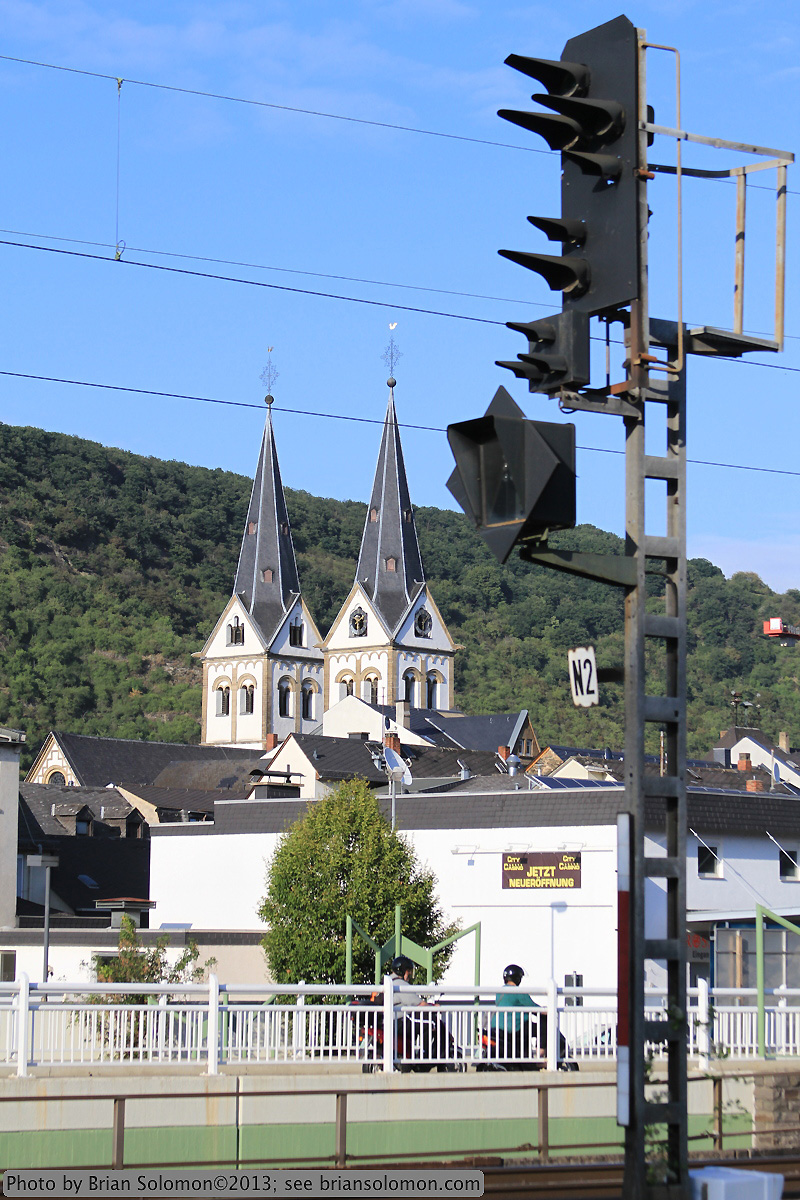 This must be what you are modelling. |
|
|
|
Post by mikejordan on Mar 28, 2015 17:14:35 GMT -5
Hi Paul
Yes, thanks - that is indeed the very signal. I didn't recognise the location at first, but when I compare it with a photo of mine, which I took from further along the platform, I recognise the two fences.
On the mast, there's an N2 plate. Any idea what it means?
In the picture, there's a multiplex board. I don't think I'll be able to get a working multiplex board in N gauge, though, or will I?
Mike
|
|
|
|
Post by Paul Harman on Mar 29, 2015 7:21:57 GMT -5
I think that a working Zs3 matrix board is pushing it for N gauge. The prototype signals that I have seen tend to only be fitted with the exact number of lamps to show the required indication so it might be possible to do something with a fibre optic or tiny LED and a stencil. I don't know the location but there is a good chance that all routes from the signal are via a diverging point so there will always be a restricted speed shown when it is cleared (just display with the green light). Speed indicated is ten times the number displayed in Km/h and just applies to the points following the signal. If you dispatch all your trains through the straight route through all the points you can just make a dummy. Not sure that anyone will notice if it works or not!
The group of three triangular (white) lamps is only used when the main signal is inoperative (presumably during engineering work) and indicates to pass the signal, or if flashing to pass the signal and proceed 'wrong line'. There should be no need to make it work.
The 'N2' plate is just the signal identification number and the one on the track to the right of it will probably have an 'N1' plate. To number the signals is quite straightforward:-
- On entry to the station (in the kilometerage direction) the signals will have 'A' prefix for the first, 'B' for the second etc.
- On exit the prefix starts at 'N' The number is just the track number, presumably in this case numbered from the right.
- In the other direction entry signals start where the other direction left off perhaps starting at 'F'.
- The same with exit signals perhaps starting at 'P'
The vertical red and white plate on the mast is important and denotes the type of signal.
You just need to make a site visit, take some photos of the number plates and a bit of video to see all the Zs3 indications (if you are going to model them).
I suspect in practice it will be a lot simpler to do than it looks at first glance and good results will be possible without doing too much work (if any) to the Viessmann signals.
|
|
|
|
Post by mikejordan on Feb 15, 2017 16:23:27 GMT -5
Hi Paul
I'm using an NCE Powercab v 1.65 and bought an SC1 (from Coastal DCC) and a Viessmann 4413. I thought I would see if that combination works for me before I commit to buying more SC1s and signals. I know little about electronics, little about signalling and not much about computing.
In your reply to my post on 22nd March 2015, you told me that the Viessmann 4412 was of the common anode type and I'm assuming that the 4413 is the same. It appears from your manual (issue 3 North America rev 1) that there are two methods of connecting the signal to the SC1 and configuring it. The first is to connect the common wire to terminal 'k' as shown in figure 9 on page 8 and set CV35 to 255 as instructed at the top of page 20. The second is to connect the common wire to terminal 'a', as instructed on pages 3, 4 and, presumably, leave CV35 set to 0.
I'm hoping that when I do use the Powercab to enter a value in a CV, the SC1 is accepting it, but as the Powercab can't read the CVs, I have no way of checking other than to observe the behaviour of the lights.
As the first method is the one suggested in your post, I used it first – common wire to 'k', CV35=255 - with the result that all the lights were off. I set CV38 to 64 and CV1 to 26, so that the address of the red light should be 26 x 4 – 3 = 101. I then selected accessory 101 and switched it on and off, which had no effect. Then I changed CV37 to 128, thinking it should set the default state of the red light to 'on'. This had no effect either.
I decided to use the second method – common wire to 'a', CV35=0 - with the result that all the lights came on. When I entered USE PROGRAM TRK, all the lights went out and then came back on after a second. That's the only evidence I have that the SC1 is responding to any of my button presses. Again, I selected accessory 101, switched it on and off and again this had no effect. Changing CV37 to 128 had no effect either, so I set it back to 0.
Thinking that setting the decoder address to 26 hadn't set the first accessory address to 101, I used the jumper method. This had no effect either, but now the SC1 may be in output address mode.
As an aside, if I'm not using the extended protocol, I have a block of 8 addresses, one for each light, so what's the difference between CV38 = 8 and CV38 = 64?
I can't help thinking I'm missing something vital, a key that will solve this mystery.
I'd be grateful for any suggestions, as I'm beginning to think that signalling is a step too far for me.
Yours
Mike
|
|
|
|
Post by Paul Harman on Feb 15, 2017 18:58:07 GMT -5
Hi Mike
A couple of things:-
First you need to connect the common to the 'a' terminal, and set CV35 = 255 to match (CV35=0 goes with connecting common cathode to the 'k' terminal).
CV38=64 uses a truth table (with two addresses for each signal), whereas CV38=8 uses a separate address for each lamp (four addresses for each signal).
|
|
|
|
Post by mikejordan on Apr 21, 2017 4:06:33 GMT -5
Hi Paul Thanks for the tips. Once I'd realised I could use JMRI DecoderPro3 to program the SC1, I managed to get it working just right. See the video here. www.dropbox.com/s/7g1gl5bi9br77bu/Movie4PH.wmv?dl=0Just one thing though: Occasionally, the SC1 returns CVs to their default values and I have to reprogram it. | CV | returns to | when I've set it to | | 1 | 1 | 101 | | 29 | 128 | 192 | | 35 | 0 | 255 | | 37 | 0 | 32 | | 38 | 0 | 135 |
However, CVs 192, 193, 194 and 195 do not lose their settings of 192, 48, 32 and 136 respectively. This loss of settings must be in response to some event (such as a short caused by a loco negotiating a wrongly set turnout?) but I haven't managed to track it down. The SC1 is connected directly to the track bus. The middle picture of Figure 7 of your manual shows the use of a circuit breaker. Would this help? If so, which one would you recommend? Yours Mike |
|
|
|
Post by Paul Harman on Apr 24, 2017 17:15:55 GMT -5
Hi Mike
It looks like you might have a faulty SC1. Probably an old version of firmware. The CVs that are being reset are ones that are set by a factory reset normally. This is not something that normally happens so please send it back and I will have a look at it and if necessary replace it.
Paul
|
|


